Naval Architecture
"Those who fall in love with practice yet without science are like a sailor who steers a ship without helm or compass, and who never can be certain whither he is going"
Leonardo da Vinci
Naval Architecture is the science behind the art of yacht design and is a relatively young discipline at least in the form that it is practiced by naval architects working on sailing and motor yachts today. The hard data to back up and further develop the theory behind the way a sailboat works only began to become available to designers in the early 70s. The model tank testing that created the Delft model series began in 1974. Ten years on a few leading designers had just begun to use computers for drafting and hydrostatic calculations. So, computer aided design (CAD) of hulls and appendages has been in general use for barely thirty years and computational fluid dynamics (CFD) other than for those with IACC or superyacht budgets for far less. Barely twenty years ago, we were the first designers to use model testing or CFD to design an IMOCA Open 60. We now make all that experience in analytical design available to clients, designers, engineers, yards and contractors for their and our own projects. OC continue to invest time and resources to develop our knowledge and access to the latest CFD and velocity performance prediction (VPP) software and when relevant we still use scale model testing. As costs have reduced, we now use CFD in all our work, from modest racing yacht to superyacht designs.
Credit: Mark Lloyd
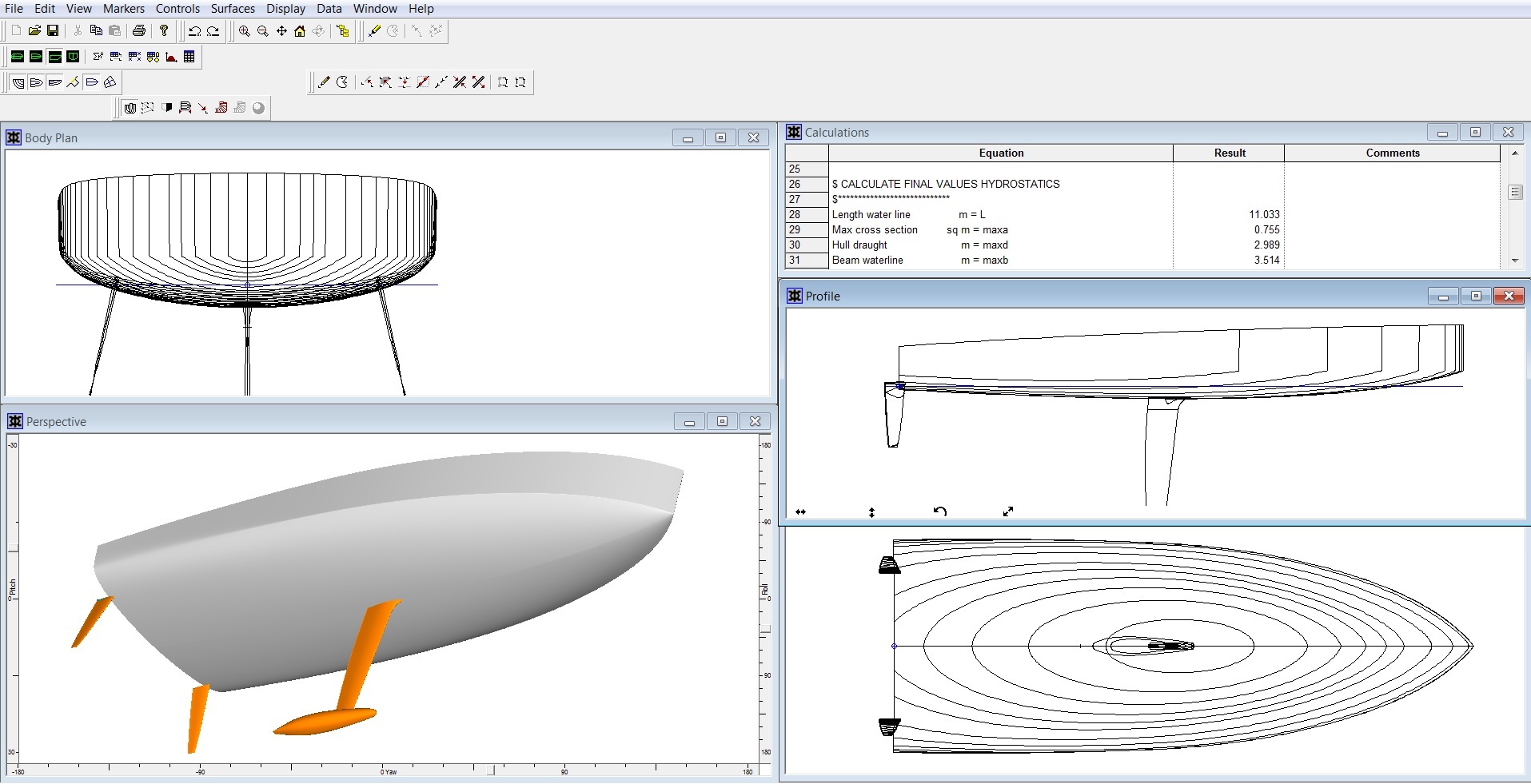
OC have been using Maxsurf, the world’s leading yacht design software since drawing the lines of our first racing boat, the 35’ trimaran Fiery Cross, in 1987. Maxsurf has since been developed further for use in the design of commercial craft and warships. It is a powerful 3-dimensional surface modelling system allowing for systematic and rapid optimisation of hull lines, appendages, decks and superstructures. With a customised interface, Maxsurf generates hull forms to high degrees of complexity, including curves and dynamically trimmed surfaces. The highest number of surfaces we have modelled so far as part of a hull, appendage and deck is seventy-two. Deliverables are hull lines, tanks, watertight compartmentation, tables and transfer files for 2D/3D drafting programs and naval architecture design suites such as Hydromax. Design analysis of either a new yacht or modification of an existing design in respect of hull, appendage or rig/sail plan requires an understanding of the fundamental parameters of its geometry such as wetted surface area, waterline beam, prismatic coefficient, righting moment, etc. In order to undertake this work, we transfer hull, deck, superstructure and appendage files to another program in our yacht design suite called Hydromax.
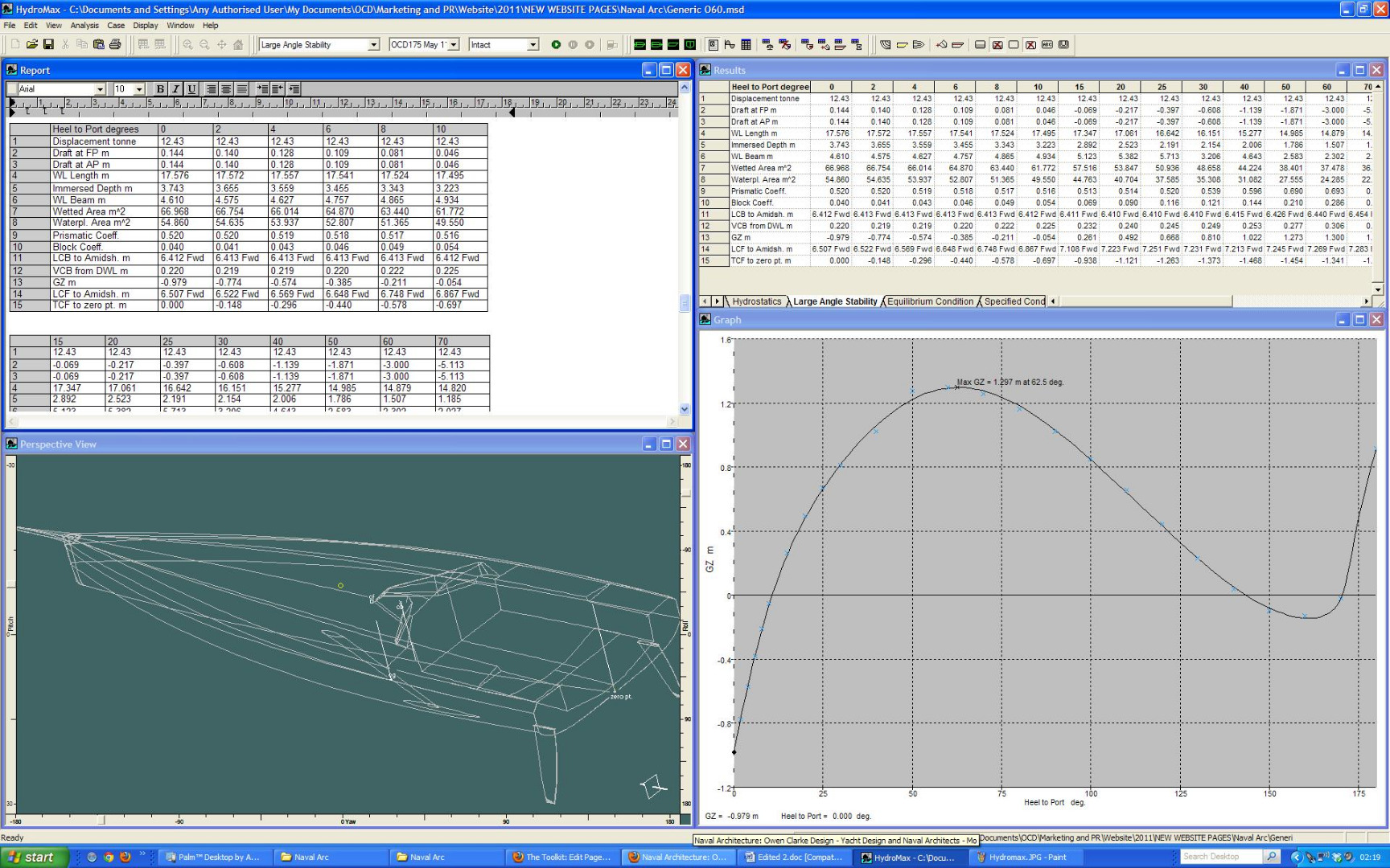
OC uses Hydromax to study a sailing or motor yacht’s static behaviour at large angles of heel up to 180 degrees. Stability curves and other hydrostatic information for upright and heeled conditions are generated by the software. The model’s displacement can be at lightship, sailing trim or any other combination including tanks and/or watertight compartments flooded. This produces righting and flooding data that is used to create the stability book as part of MCA requirements, conform with the Recreational Craft Directive (RCD) and is used by rating offices and racing class measurers. The data is also read by VPP (velocity performance prediction) programs and used for the adjustment of certain characteristics of the yacht. For instance, the addition of lead in a keel bulb, or water ballast in a wing tank can be calculated as a result of the changes to a yacht’s trim, displacement, center of gravity and righting moment. The design circle is closed when Hydromax calculates the effect of changes on the hydrostatic characteristics of the yacht, and feeds this information back into the VPP software. The relative negative/positive effect on drag of wetted surface area, trim, waterline beam etc, against the righting moment/stiffness (which can be equated to thrust) is analysed by the VPP program.
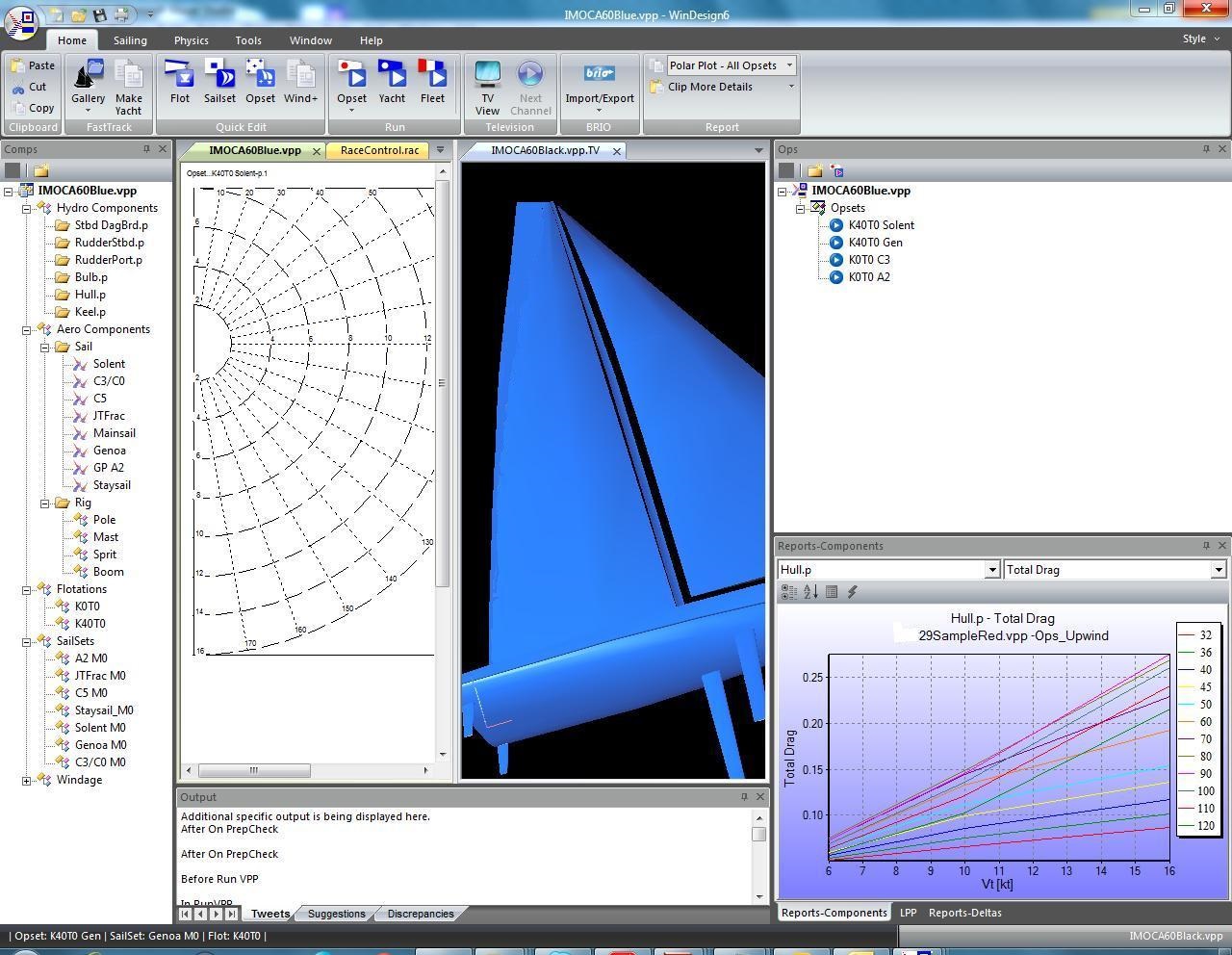
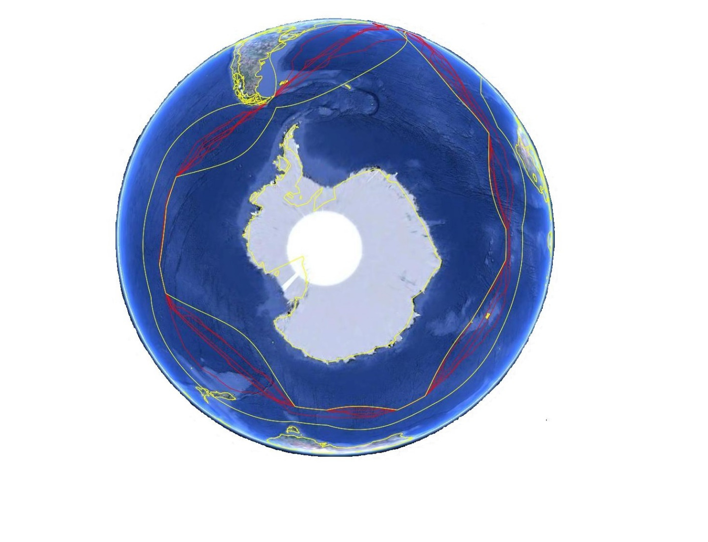
The prediction of a yacht’s behaviour using VPP software is applicable throughout the design process from preliminary studies, to complex analysis of tank/wind tunnel/CFD results and final hull, appendage and rig/sail selection. We often analyse designs in different weather scenarios using either our database or weather data supplied by the project team. The software can determine accurately the daily passage making qualities of a cruising yacht as well as optimise a yacht for inshore, Atlantic or round the world races. The benefits of changes are easily recognised referencing outputs such as; yacht polar diagrams, boat speed, sail/ballast cross-overs, mainsail reef conditions etc. The program is very flexible and as well as for all our own designs we have used it many times in consultancy work for others. An early and challenging example was for the 2001 America’s Cup Jubilee Regatta at Cowes for which OC designed a new foil package for USA 61 (Tom Blackaller’s Freemantle Americas Cup 12 metre with the twin rudder system), after analysis using the vpp with ten years averaged weather for the East Solent. A more mainstream study for us would be sail damage scenarios and the affect this would have on different races for IMOCA 60s and Class 40s, given their sail wardrobe rule limitations.
In addition to analysing designs using the internal tools within WinDesign, for over a decade OC have been using Router race modelling software developed for the Volvo Ocean Race. Router uses the polars and cross-over information developed by the VPP combined with actual historical weather data (GRIB files) to compare candidate designs on race courses or on passage between point A and B. As well as the obvious Vendee Globe, Route du Rhum and TJV courses for our IMOCA 60 and Class 40 designs we have analysed the performance of IRC/ORC racing yachts and superyachts in events such as the Fastnet, Sydney-Hobart, Newport-Bermuda and Cape-Rio races. The output data from the program includes the distance sailed and the time spent sailing by the yacht in a matrix of true wind angles and true wind speeds during any given race. Also, which sails, ballast or trim conditions are used and for cruising yachts how long one might need to run the main engine to achieve a given passage making speed. OC use Router during the design of new yachts, modification of existing designs, sail plan and sail wardrobe development and we were the first design office to run Router with weather files in GRIB format which greatly improved the quality of the output data from the program.
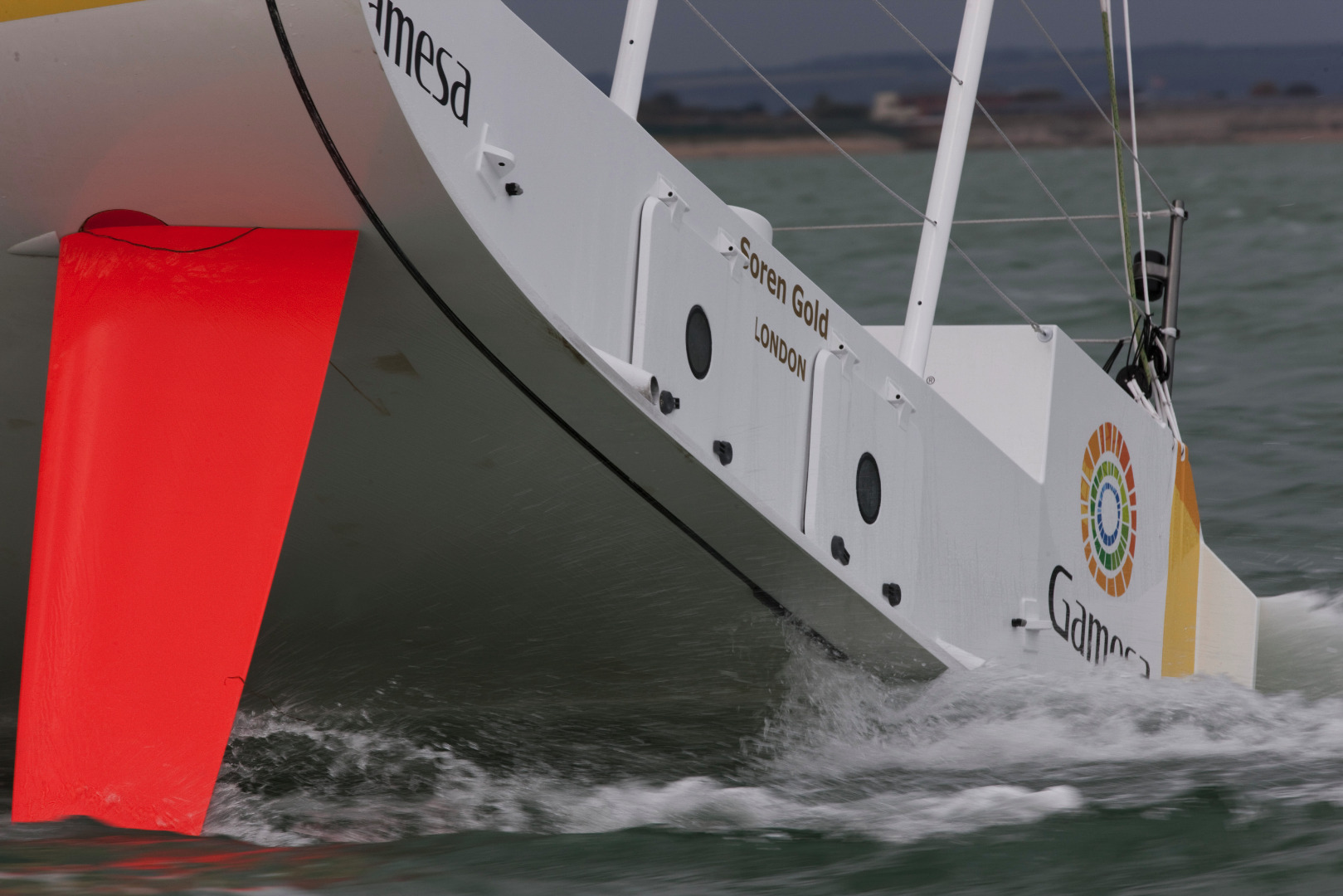
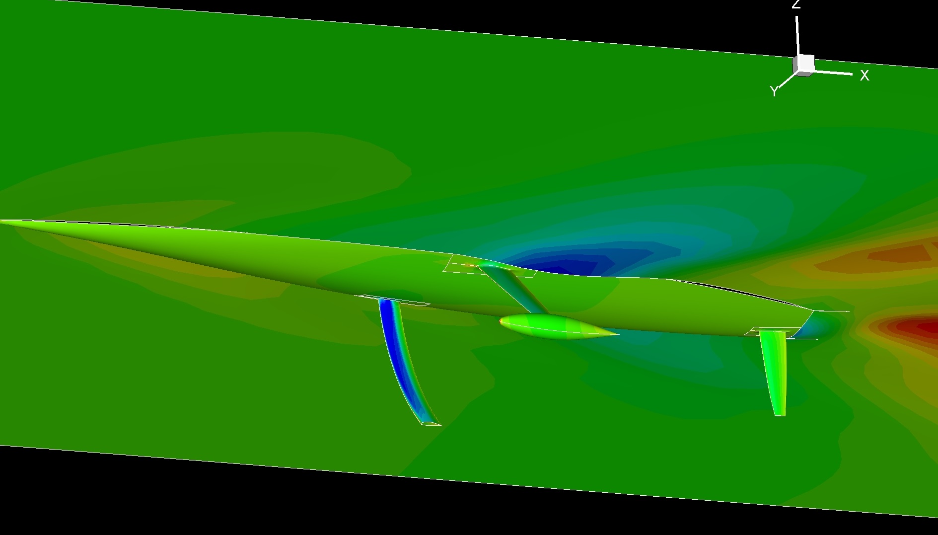
When not using test data, VPP software is restricted to its internal mathematical algorithms to calculate values of aero/hydro lift and drag. In broad brush terms they do this very well and for similar hull forms and rig types the results provide good indicators of comparative performance. However, there is a limit to the accuracy of any generic VPP that relies on its own algorithms. The analysis for a moderate displacement IRC/ORC 45 with a relatively standard hull form (not greatly dissimilar from those used in the Delft series of model tests from which most VPP internal algorithms are derived) is quite different from an IMOCA 60 or high speed, high Froude number racing yacht, with foils, canting keel and/or T foil rudders (see photo). A design office that uses model testing has access therefore to more reliable data for input into any VPP analysis. The result is that the likelihood of error is eliminated when comparing different designs, and outputs such as speeds, sail cross-overs etc are more accurate. In the bigger picture, model testing, particularly for larger, higher budget projects is very cost effective. They allow a design office to be more innovative by mitigating risk, confirming hypothesis and eliminating the possibility of a ‘bad idea’ from reducing the performance of an otherwise fast design.

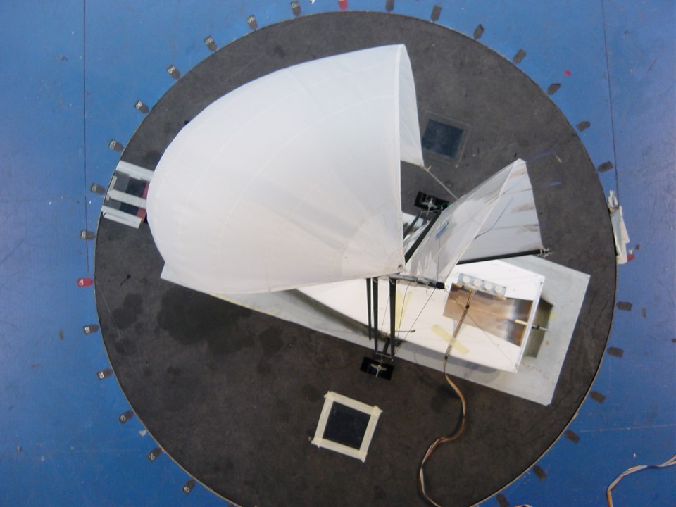
Wind tunnel testing has for the most part now been replaced by computer simulation. However, for complex sail-plans such as schooners and for slower designs that sail downwind at low angles of attack with separated flow, it remains a good alternative. Model testing helped OC introduce many innovative design ideas into the IMOCA Open 60 class for the first time with confidence. Many are now common to all 60's, including the three forestay sailplan (Kingfisher), the masthead rig and the use of reaching struts (Ecover 2). OC have used both the
Wolfson Unit
and
University of Auckland
tunnels, each having different characteristics and strengths. At the Wolfson it is a closed loop high speed tunnel that creates stable, consistent conditions making it superior for the development of lift/drag curves used in VPP modelling. The Auckland tunnel is non-circulating with twisted flow, specifically designed for sail testing. Vertical twisting vanes at the duct outlet enable the flow in the test section to be varied in a controlled manner with height so that the apparent wind speed and direction onto the sails which varies at full scale can be simulated in a wind tunnel test on a stationary model. We’ve found this tunnel very useful to compare sails on the same model as well as interacting with sailors at the test.
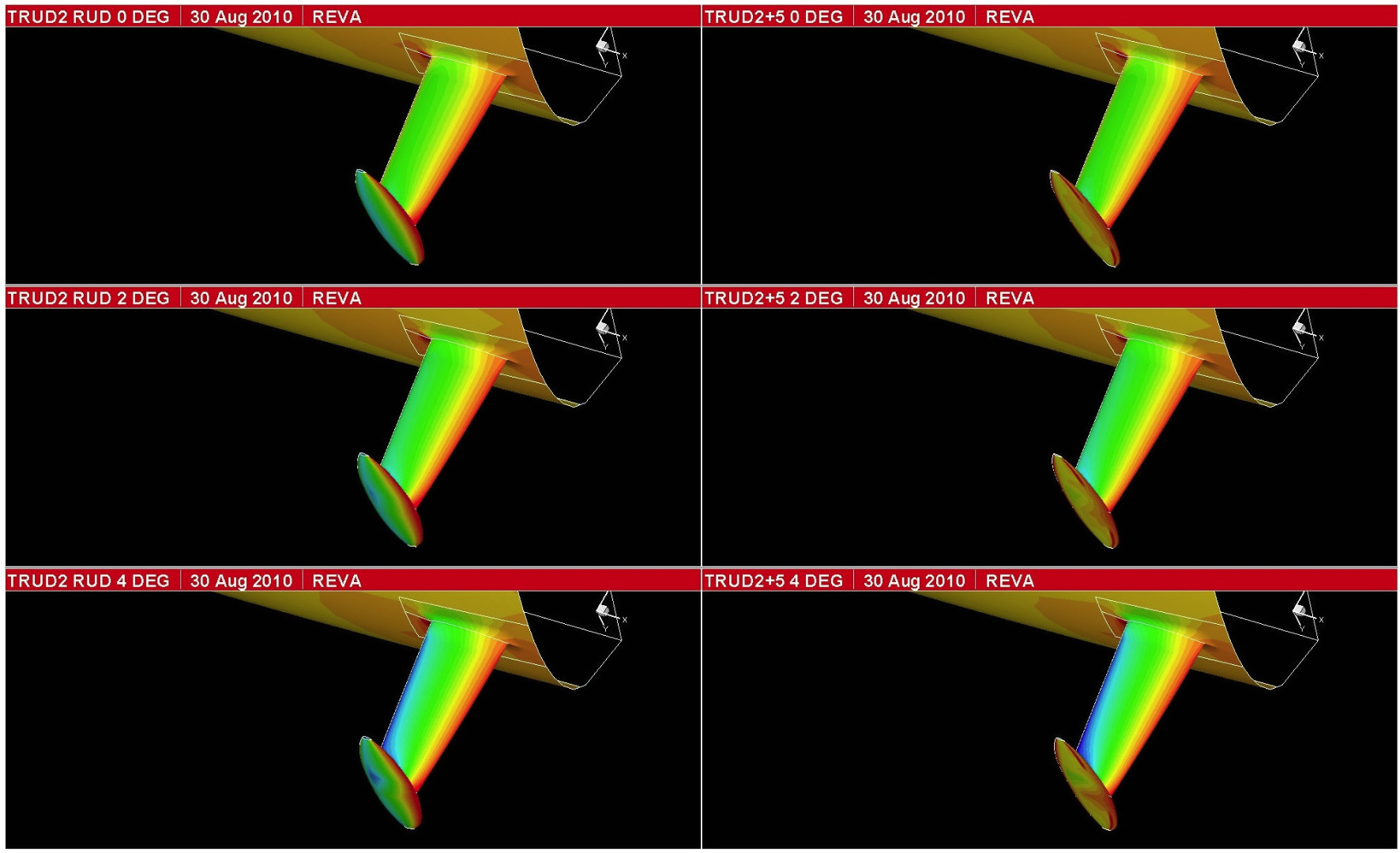
CFD is the study of fluid mechanics that uses numerical methods to solve and analyse flow. Computers are used to perform the calculations required to simulate the interaction of fluids with surfaces, in the case of yacht design; appendages, hulls, sails and spars. With the advent of high-speed and lower cost computing CFD is applied to many more problems and on smaller budget projects than ever before. Owen Clarke Design has been using CFD as a tool since the design of Kingfisher in 1999. Since then all our major R and D programs have included CFD analysis. Our smaller, lower budget projects have benefited from that research, particularly in terms of rudder, keel and sailplan design. The graphic shows the pressure distribution on an IMOCA 60 hull with curved foils, modelled using RANS solver based software, CFX. Although the hull and appendages were both modelled, compared and calibrated against the tank test results, the primary aim of the investigation was the interaction of the three appendages, distribution of side/lift forces and the optimisation of their attack angles. One of the advantages of CFD over model testing is this ability to look at the lift forces and centres of pressures on individual appendages and sails in detail, as well as providing a visualisation of the results.
Historically CFD’s weak point has been modelling free surface effects and the calculation of drag, particularly for high speed, high Froude number hulls, tasks that scale model testing is very good at. However, with the passage of time, considerable resource and more projects whereby CFD predictions could be compared with tank and full-scale data-logging, confidence in determination of drag for high speed planing hulls is now comparable to scale model testing. CFD software varies widely in both cost (be that rental, purchase, licence fee) and application. The more expensive RANS based solvers are mainly applied to complex tasks, such as problems which involve a free surface between two fluids (e.g. water and air) and variable trim. Solving for free surface affects, waves, wake simulation etc requires RANS code, while calculating solutions for a single fluid is less complex. Rudders, keels and bulbs can be dealt with by less time consuming and cost-effective panel code software such as X-foil. Panel code is also effective when used for a range of fixed trim, speed, heel and yaw investigations of a hull to understand better and limit the size of a test matrix for that hull prior to using a RANS solver.
CFD was first used in the aerospace and aeronautics industries, so for naval architects it is not only a tool for development of hulls, keels, rudders and foils, but also for spars and sail-plans. Through a long association over a number of years with high technology suppliers such as Southern Spars and North Sails France our clients have benefited from the use of CFD based aero software packages such as Flow and Membrane. Most of our 60’ and 40’ sail wardrobes have been developed using this software and it has been used to help define sailing loads in rigging, sheets and halyards since first used for the design of our IMOCA 60, Ecover 2 in 2003. The cost of using CFD has reduced significantly over time and is now used across the full range of our work. We continue to monitor developments in CFD, are invested in it and advise clients where it’s appropriate and cost effective to use. Auto-meshing tools and Cloud based software have cut processing times and cost in recent years, now bringing affordable hull force solutions within the reach of cruising yacht budgets. We are using CFD on our current twin hybrid drive motor sailer to evaluate powering requirements and recently completed a CFD and VPP consultancy that delivered new keel and rudder designs for this modern classic yacht

For information regarding engineering services we offer go to:
ENGINEERING
For an overview of services we've provided on past projects go to:
CONSULTANCY
|